Home

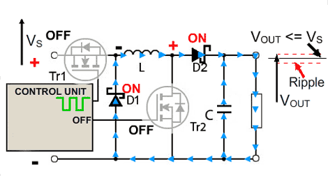
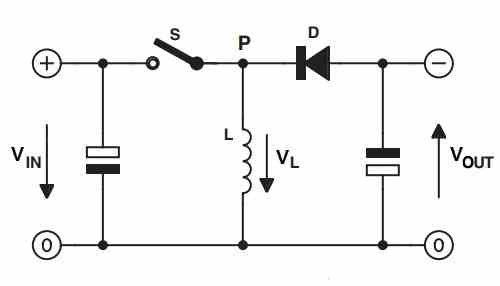
buck and boost converter

EE463 - Non-inverting Buck-Boost Converter - YouTube

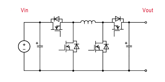
dcdc_bidir_bck_bst_050v

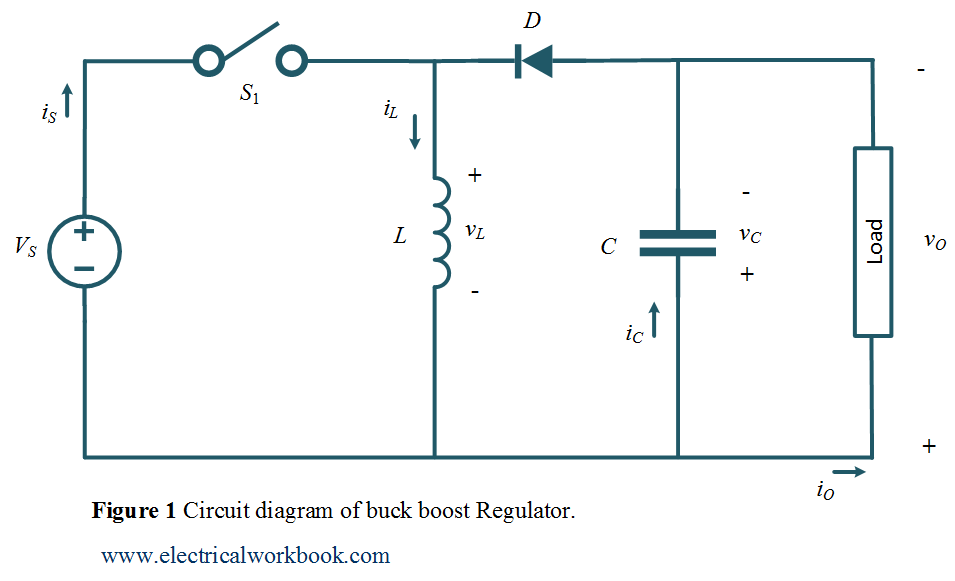
The Buck boost regulator shown in figure has an input voltage of Vs=12V.  The duty cycle is 0.25 and the switching frequency is 25 kHz. The  inductance L =150 μ H and
The Buck boost regulator shown in figure has an input voltage of Vs=12V. The duty cycle is 0.25 and the switching frequency is 25 kHz. The inductance L =150 μ H and

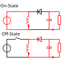
Buck–boost converter - Wikipedia

Buck–boost converter - Wikipedia

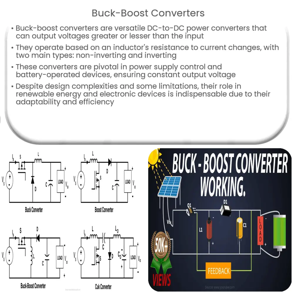
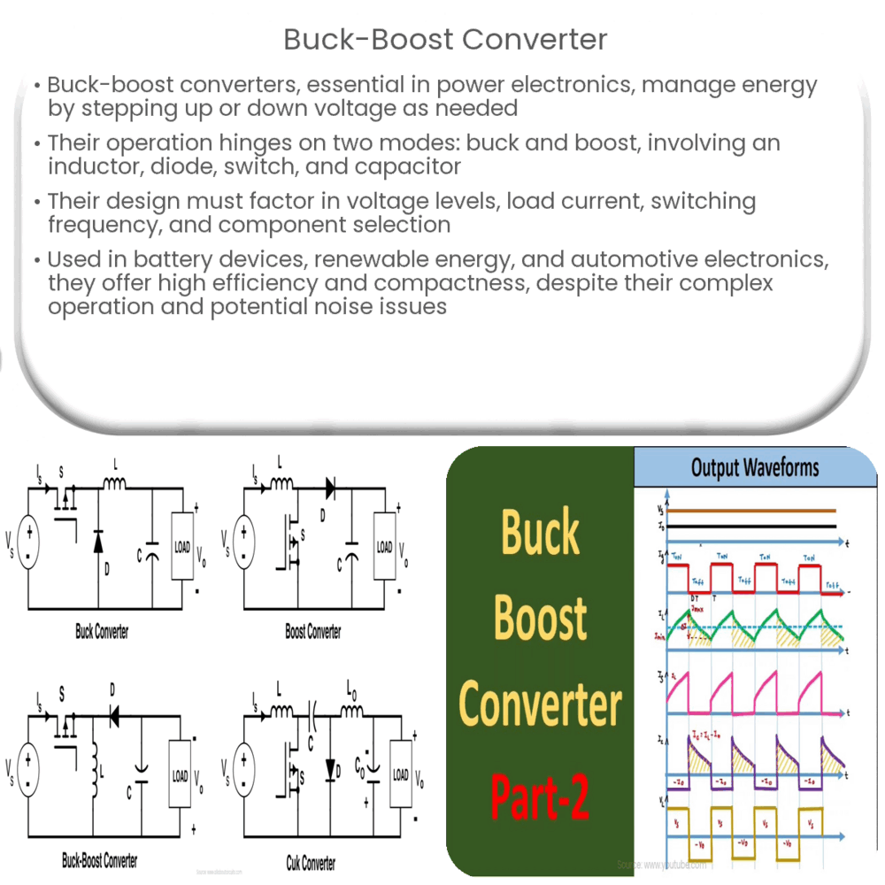
Buck-Boost Converters | How it works, Application & Advantages

Schematic diagram of buck, boost, and buck-boost converter: (a) buck... |  Download Scientific Diagram
Schematic diagram of buck, boost, and buck-boost converter: (a) buck... | Download Scientific Diagram
Buck-boost converter | How it works, Application & Advantages

Buck Boost Converter, working, principle and waveform [Hindi] - YouTube

Buck–boost converter - Wikipedia

EC8452_ELECTRONIC CIRCUITS-II_Unit 5.2 Buck-Boost Converters | PPT

Circuit representation of the DC-DC buck-boost converter with a CPL |  Download Scientific Diagram
Circuit representation of the DC-DC buck-boost converter with a CPL | Download Scientific Diagram

Buck Boost Regulator Peak to Peak Ripple Current of Inductor Expression  Derivation - ElectricalWorkbook
Buck Boost Regulator Peak to Peak Ripple Current of Inductor Expression Derivation - ElectricalWorkbook

Designing an Arduino-based Buck-boost Converter With Feedback | Arduino |  Maker Pro
Designing an Arduino-based Buck-boost Converter With Feedback | Arduino | Maker Pro

A Single-Switch Quadratic Buck–Boost Converter With Continuous Input Port  Current and Continuous Output Port Current | Semantic Scholar
A Single-Switch Quadratic Buck–Boost Converter With Continuous Input Port Current and Continuous Output Port Current | Semantic Scholar

Some properties of buck, boost and buck-boost converters. | Download  Scientific Diagram
Some properties of buck, boost and buck-boost converters. | Download Scientific Diagram

Difference Between Buck Converter and Boost Converter

Buck-Boost Converters

Do not operate a 4 switch buck-boost converter in buck-boost mode - Power  management - Technical articles - TI E2E support forums
Do not operate a 4 switch buck-boost converter in buck-boost mode - Power management - Technical articles - TI E2E support forums

Buck-Boost Converter: What is it? (Formula and Circuit Diagram) |  Electrical4U
Buck-Boost Converter: What is it? (Formula and Circuit Diagram) | Electrical4U

Development of a Four-Switch Buck-Boost Converter: Operation Modes, Control  and Experimental Results | Semantic Scholar
Development of a Four-Switch Buck-Boost Converter: Operation Modes, Control and Experimental Results | Semantic Scholar

Introduction To Buck-Boost Converter | Robu.in

Four switch buck-boost converter with buck and boost stages. | Download  Scientific Diagram
Four switch buck-boost converter with buck and boost stages. | Download Scientific Diagram

Simple Buck-Boost Converter Circuits Explained | Homemade Circuit Projects